Introduction
System failure often starts with a single incorrect component choice. You know that leakage means downtime, environmental hazards, and lost revenue for your operation. But did you know that nearly 60% of all hydraulic system leaks stem directly from improper fitting selection during the initial design or maintenance phase? Identifying the correct thread type, pressure rating, and sealing method is often a guessing game for procurement managers and maintenance teams alike. One mismatched connection does not just risk a drip; it risks catastrophic blowout and operator injury.
Here is the definitive methodology for selecting the perfect connector. This guide analyzes the ten most critical hydraulic fitting standards used globally, detailing their specific pressure capabilities, sealing mechanisms, and ideal applications. We eliminate the guesswork from your procurement process. When selecting components, partnering with a custom hydraulic fittings manufacturer ensures you meet specific ISO and SAE standards regardless of the connection type required for your machinery.
Visual Overview: Fitting Standards Compared
Understanding the fundamental differences between American, European, and Asian standards prevents costly installation errors. Here is the deal: Visual identification alone often fails because many threads look identical to the naked eye but possess different pitch angles. The infographic below provides a rapid reference matrix to categorize these components by their sealing method and pressure class.

Table 1: Hydraulic Fitting Selection Matrix
| Fitting Type | Standard Origin | Primary Sealing Method | Typical Pressure Rating | Vibration Resistance | |
|---|---|---|---|---|---|
| NPT / NPTF | USA (ANSI) | Thread Deformation | Low – Medium | Poor | |
| JIC (37°) | USA (SAE) | Metal-to-Metal Flare | Medium – High | Good | |
| ORB (Boss) | USA (SAE) | O-Ring Compression | High | Excellent | |
| ORFS | USA (SAE) | Face Seal O-Ring | Extremely High | Best | |
| BSP (P/T) | UK/Europe | Bonded Seal or Taper | Medium – High | Moderate | |
| DIN Metric | Germany (ISO) | Bite Type / O-Ring | High | Very Good | |
| Flange (61/62) | USA (SAE) | O-Ring Face | Extremely High | Excellent |
1. What are NPT and NPS Hydraulic Fittings?
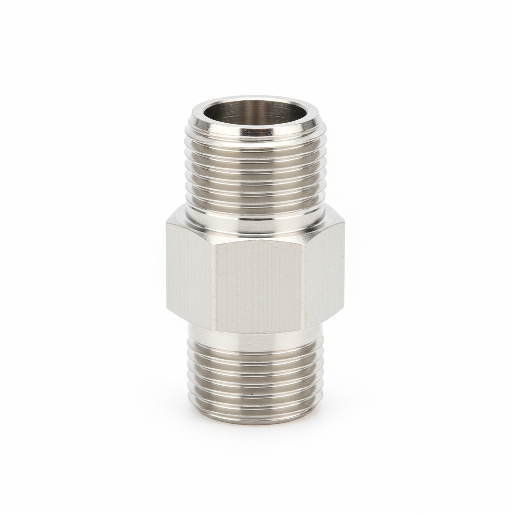
National Pipe Taper (NPT) and Nominal Pipe Size (NPS) represent the oldest and most common connection styles in North American fluid power systems. These fittings follow ANSI/ASME B1.20.1 standards and utilize a 60-degree thread angle with flattened peaks and valleys. Engineers originally designed these for water pipes, but they found a home in low-pressure hydraulic applications due to their availability and low cost. The sealing mechanism relies entirely on thread deformation. As you tighten the tapered male thread into the female port, the metal compresses, creating a mechanical seal.
But here is the kicker: This reliance on deformation makes NPT fittings prone to leakage under high vibration or thermal cycling. Over-tightening is a frequent issue where mechanics crack the female port housing while attempting to stop a leak. NPTF (Fuel) variations exist to provide a tighter seal without sealant, yet most standard NPT connections require PTFE tape or chemical sealant to ensure leak-free performance. While excellent for general plumbing or suction lines, high-pressure dynamic systems usually require more robust solutions.

Table 2: NPT vs. NPTF Technical Specifications
| Feature | NPT (National Pipe Taper) | NPTF (Dryseal) | |
|---|---|---|---|
| Thread Shape | Tapered Profile | Tapered Profile | |
| Crest/Root | Flattened | Sharp / Truncated | |
| Sealing Mode | Flank contact (Needs tape) | Crest-to-root contact | |
| Reuse | Limited (Threads deform) | Very Limited | |
| Common Use | General Hydraulics / Air | Fuel / High Reliability |
2. Why are JIC Fittings the Industry Standard?
Joint Industry Council (JIC) fittings serve as the backbone of American industrial hydraulics and agricultural equipment. Standardized under SAE J514, these connections feature straight threads and a 37-degree flare seating surface. The seal occurs not on the threads but via metal-to-metal contact between the male flare nose and the female cone seat. This design allows for repeated assembly and disassembly without damaging the fitting or the port, a significant advantage over NPT.
You might be wondering: Why do engineers prefer JIC for medium-pressure lines? The answer lies in its simplicity and reliability. Since the holding power comes from the straight threads while sealing happens at the nose, JIC adapters handle lateral loads well. However, because they lack an elastomeric seal (O-ring), they remain susceptible to weeping if vibration loosens the nut. For high-volume orders requiring specific plating like zinc-nickel to combat corrosion, request a custom quote for JIC fittings to ensure compatibility and longevity in harsh environments.
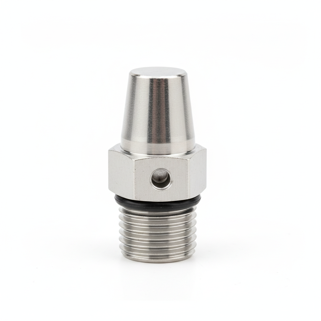
3. How Does the ORB (O-Ring Boss) Connection Work?
The SAE J1926 O-Ring Boss (ORB) fitting was engineered specifically to solve the leakage problems associated with tapered threads. Unlike NPT, an ORB connection uses straight threads strictly for mechanical holding power. The sealing duty falls to a rubber or synthetic elastomer O-ring (typically Buna-N or Viton) seated at the base of the male thread. When tightened into a chamfered port, this O-ring compresses to form an incredibly tight, leak-proof barrier that withstands significant pressure spikes.
This is where it gets interesting: Because the seal is elastomeric rather than metal-on-metal, ORB fittings virtually eliminate the “weeping” common in JIC or NPT systems. They are the preferred port connection for pumps, cylinders, and valves in modern hydraulic system design. The main limitation involves temperature; the O-ring material must match the fluid temperature and chemical composition. Users must ensure the O-ring is not pinched during installation, which would compromise the seal immediately.
4. What Makes ORFS (O-Ring Face Seal) Superior for High Pressure?
O-Ring Face Seal (ORFS) fittings, defined by SAE J1453, represent the pinnacle of leak prevention for high-vibration environments. The design features a flat-faced male fitting with a machined groove that houses an O-ring. The female connection is also flat-faced. When the nut tightens, it compresses the O-ring between the two flat surfaces, creating a “soft” seal that tolerates immense vibration and thermal shock without loosening or leaking.
Here’s the catch: While ORFS fittings offer the highest pressure ratings—often exceeding 6,000 PSI—they require precision alignment. The flat faces must meet perfectly parallel; otherwise, extrusion of the O-ring might occur. Construction equipment, excavators, and mining machinery rely heavily on ORFS because these applications involve constant shaking and pressure surges that would crack a flare fitting. They serve as a “zero-leak” solution where environmental protection is paramount.
Table 3: Vibration Resistance Comparison
| Fitting Style | Vibration Handling | Failure Mode | |
|---|---|---|---|
| ORFS | Excellent | O-ring extrusion (rare) | |
| JIC 37° | Moderate | Nut loosening / Flare crack | |
| NPT | Poor | Thread root cracking | |
| Bite Type | Good | Ferrule slip |
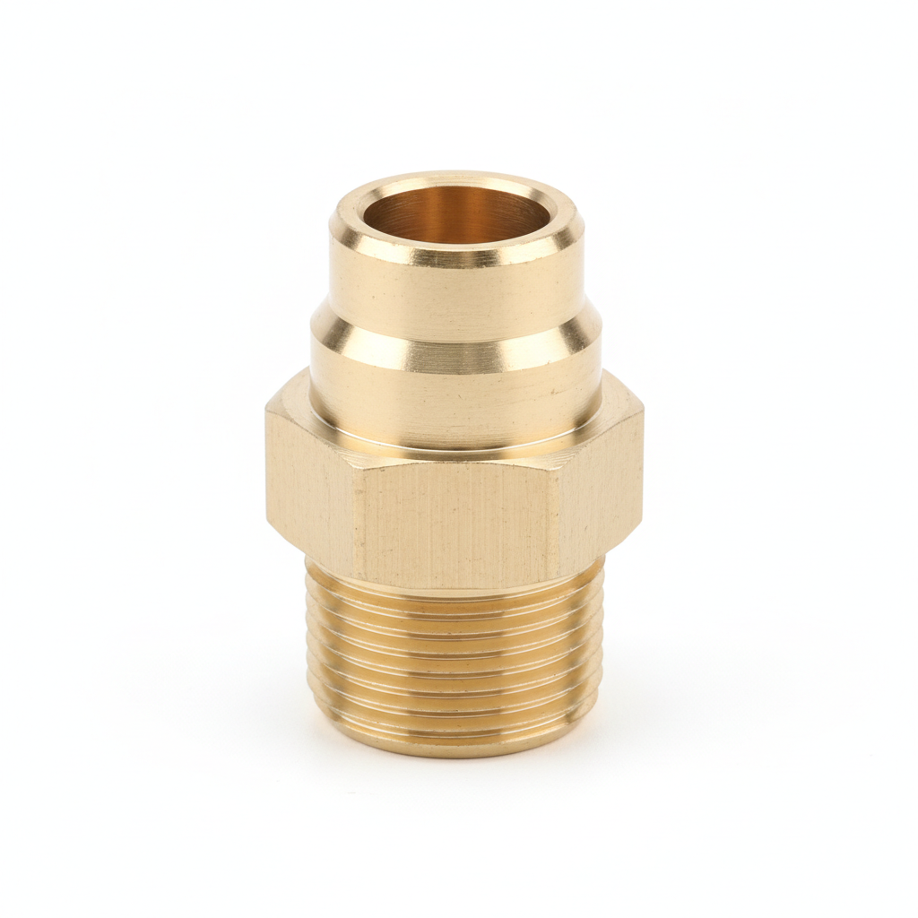
5. How Do BSPP and BSPT Fittings Differ?
British Standard Pipe (BSP) threads dominate the fluid power landscape in Europe, Asia, and Australia. If you import equipment from the UK or China, you will undoubtedly encounter these. They come in two distinct flavors: BSPP (Parallel) and BSPT (Tapered). Both utilize a 55-degree Whitworth thread angle, which makes them incompatible with American NPT (60-degree) ports. Forcing a BSP fitting into an NPT port will strip threads and ruin components instantly.
What’s the real story? BSPP fittings, often called “G” threads, function similarly to ORB; they require a bonded washer or an O-ring to seal against the face of the port. BSPT, or “R” threads, function like NPT, sealing via thread deformation on the taper. Identifying the difference requires a thread gauge and a caliper. Mistaking a parallel thread for a tapered one leads to catastrophic blowouts because the parallel thread will screw in but never actually seal without the required washer.
6. When Should You Choose Metric DIN Fittings?
German industry standards (DIN 2353 and ISO 8434-1) established the metric “bite type” fitting, which is prevalent worldwide in mobile equipment and industrial machinery. These fittings use a 24-degree cone seat. The sealing mechanism typically involves a cutting ring (ferrule) that bites into the tubing wall as the nut tightens, or a DKO cone which includes an O-ring for superior sealing. They are categorized into three series: LL (Extra Light), L (Light), and S (Heavy), depending on the pressure requirements and tube wall thickness.
Ready for the good part? The “S” series DIN fittings handle extreme pressures that rival or exceed SAE standards, making them ideal for heavy-duty earthmovers. Their metric sizing makes integration with modern global components seamless. For corrosive marine environments often utilizing DIN standards, stainless steel hydraulic adapters provide the necessary longevity and safety against saltwater corrosion. The precise engineering of DIN fittings allows for compact system design without sacrificing power density.
7. What are the Advantages of Code 61 and 62 Flanges?
Threaded connections face a physical limit. As tube diameter increases, the torque required to tighten a threaded fitting becomes unmanageable for installation teams. Enter the SAE J518 4-bolt flange. Designed for pipes and tubes ranging from 1/2 inch up to 3 inches or more, flanges use four bolts to pull two flat faces together, compressing an O-ring. This design separates the holding force (bolts) from the sealing force (O-ring), allowing for massive hydraulic power transmission without massive wrenches.
But here is the twist: SAE Flanges come in two incompatible classes. Code 61 is the “standard” series, typically rated for 3,000 to 5,000 PSI depending on size. Code 62 is the “high pressure” series, rated for a constant 6,000 PSI across all sizes. The bolt hole patterns differ, preventing accidental cross-connection. You must measure the bolt-to-bolt distance accurately. Caterpillar also uses a proprietary version of Code 62 with a thicker flange head, adding another layer of complexity for replacement part sourcing.
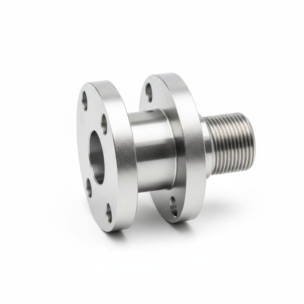
Table 4: SAE Flange Code 61 vs. Code 62
| Characteristic | Code 61 (Standard) | Code 62 (High Pressure) | |
|---|---|---|---|
| Pressure Rating | 3000 – 5000 PSI | 6000 PSI (Constant) | |
| Bolt Application | Standard Hydraulic Lines | Hydrostatic Drives | |
| Visual ID | Thinner Flange Head | Thicker Flange Head | |
| Bolt Spacing | Rectangular (Smaller) | Rectangular (Larger) |
8. How Do Bite Type Fittings Secure the Connection?
Bite type fittings, often referred to as flareless compression fittings, offer a robust solution for thick-walled tubing where flaring the tube end is impossible or impractical. The assembly consists of a body, a nut, and a hardened ferrule (cutting ring). As technicians tighten the nut, it drives the ferrule forward into the tapered throat of the fitting body. The geometry forces the ferrule to bite down into the outer diameter of the tube, creating a ridge of material that locks the tube in place and forms a seal.
You might assume: That welding is the only way to secure heavy-wall pipe. However, modern bite type fittings provide holding power comparable to a weld without the fire hazard, x-ray inspection, or skilled labor required for welding. They are field-repairable and reusable if the tube is not damaged. Proper presetting of the ferrule is critical; under-tightening results in blow-off, while over-tightening crushes the tube. They are standard in Asian and European machinery designs.
9. Where are Hydraulic Weld Fittings Used?
Socket weld and butt weld fittings eliminate potential leak paths by fusing the connector directly to the manifold or pipe. In applications involving extreme pressures (10,000+ PSI), radioactive fluids, or temperatures that would melt rubber O-rings, welding becomes the mandatory joining method. Socket welds involve inserting the pipe into a recessed socket before welding, while butt welds join two flat faces. These connections are permanent and offer the highest structural integrity of any fitting type.
Here is the reality: While leak-proof, weld fittings demand significant labor and skill. The welding process can introduce contaminants (slag) into the hydraulic system if not performed carefully. Furthermore, replacing a component requires cutting and re-welding, leading to extended downtime. Reliable weld fittings rely on a precision CNC machining process to guarantee thread tolerances and weld bevels are exact, ensuring the welder has a clean, consistent surface to work with.
10. Can Push-to-Connect Fittings Handle Hydraulics?
Push-to-connect (PTC) fittings are ubiquitous in pneumatic (air) systems due to their convenience—you simply push the tube in, and it locks. Historically, these were considered too weak for hydraulics. However, recent engineering advancements have introduced metal PTC fittings designed for low-pressure hydraulic pilot lines and case drain circuits. They utilize internal stainless steel grab claws and high-durometer O-rings to handle pressures up to 300-500 PSI, depending on the design.
Check this out: While you would never use a PTC fitting on the main hydrostatic drive of an excavator, they are game-changers for diagnostic equipment and low-pressure return lines where speed of assembly is critical. They eliminate the need for wrenches in tight spaces. However, users must be extremely careful not to confuse pneumatic-rated plastic fittings with hydraulic-rated metal ones. Using a plastic air fitting on an oil line is a recipe for immediate failure and an enormous mess on the factory floor.
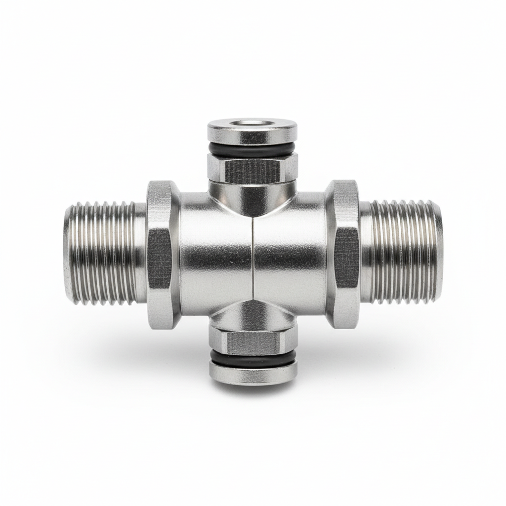
Table 5: Push-to-Connect vs. Threaded Fittings
| Feature | Push-to-Connect | Threaded (JIC/ORB) | |
|---|---|---|---|
| Assembly Speed | Instant | Slow (Wrench needed) | |
| Pressure Limit | Low (<500 PSI) | High (>5000 PSI) | |
| Tooling | None | Spanners / Torque Wrench | |
| Primary Use | Pilot Lines / Diagnostics | Power Transmission |
Summary & Next Steps
Selecting the correct hydraulic fitting is not merely about matching thread sizes; it is about matching the component’s capabilities to the system’s operational stresses. Pressure (PSI), vibration intensity (ORFS vs. JIC), and geographical origin (Metric vs. NPT) dictate the safe choice. Ignoring these factors leads to leaks that drain budgets and compromise safety. Always verify thread pitch with gauges and consult pressure charts before installation.
Don’t guess on specs. Precision is the only safety net in fluid power. For more technical guides on maintenance, assembly torques, and troubleshooting, visit our hydraulic industry insights section. If your operation requires reliable, standard-compliant components, contact our engineering team today to secure your supply chain against failure.
Frequently Asked Questions
Q1: Can I interchange JIC 37° and SAE 45° flare fittings?No, you cannot safely interchange them. While the threads might appear similar in some sizes, the seat angles are different (37 degrees vs. 45 degrees). connecting them creates a gap at the sealing surface, guaranteeing a leak. JIC 37° is the standard for high-pressure hydraulics, while SAE 45° is typically found in low-pressure automotive fuel or HVAC lines.
Q2: Why do my NPT fittings leak even after tightening?NPT threads rely on metal deformation to seal, which is imperfect. If they leak, it is often due to poor thread quality, lack of sealant, or over-tightening which distorts the female port (cracking it). Always use a high-quality thread sealant or PTFE tape, and follow the “turns past finger tight” installation method rather than just torque.
Q3: How do I distinguish between BSPP and BSPT threads?You need a caliper and a visual inspection. BSPP (Parallel) threads have a constant diameter from the start to the end of the fitting. BSPT (Tapered) threads get narrower at the tip. Additionally, a BSPP fitting will usually have a visible chamfer or spot face to accept a bonded washer, which BSPT fittings lack.
Q4: What is the main benefit of using O-Ring Face Seal (ORFS) over JIC?The primary benefit is leak resistance under high vibration. JIC metal-to-metal seals can loosen or mar when subjected to constant shaking or pressure spikes. The elastomeric O-ring in ORFS fittings absorbs this vibration and maintains contact, providing a “dry” system even in severe heavy-equipment applications.
Q5: Are stainless steel fittings required for all hydraulic systems?Not necessarily. Carbon steel is sufficient for most indoor and standard industrial applications involving hydraulic oil. Stainless steel is required for marine environments, corrosive chemical processing, or food production where wash-down occurs. Using stainless steel unnecessarily increases costs, but using carbon steel in a corrosive zone risks safety.